“Survey Design” panel
The “Survey Design” panel (Fig. 11) allows to manage the FullWaver survey project, by defining the configuration of receivers and transmitters.
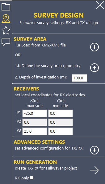
Fig. 11 Survey design panel.
The panel is made of four sections and the configuration parameters are usually specified following a top-to-bottom order.
“Survey area” section
Contains the commands to define the layout of the area or profile to be investigated.
1.a Load from KMZ/KML file
Opens the dialog to select a KML or KMZ file with the area (polygon) or the profile (polyline) for the project design. If multiple graphic objects are stored into the file, only the first occurrence will be taken into account. The layout of the area to be investigated will be shown on the map of the Project summary tab. The map makes use of UTM coordinates, with conversion based on the ellipsoid defined in the Preferences panel (default is WGS84).
1.b Define the survey area geometry
When a KMZ or KML file is missing, use this command to access the Define survey area panel to generate simple linear or rectangular survey geometries.
2. Depth of investigation
Specify in this text box the desired depth of investigation in meters. Of course, as you increase the required depth of investigation the length of the TX dipoles will consequently increase (typically the ratio of depth of investigation vs TX extension is 1:5).
“Receivers” section
Define in this section the spacing of the RX electrodes of the V-FullWaver boxes.
The geometry of the electrodes is defined for each box in a reference system local to the P2 electrode, which has always (0.0, 0.0) coordinates. The logic of receiving electrodes geometry is based on the following convention:
- the x axis of the local reference system is aligned along the direction of the survey area with the major extension;
- the y axis of the local reference system is aligned along the direction of the survey area with the minor extension.
For example, setting P1 coordinates to (-15.0, 0.0) and P3 to (15.0, 0.0) will arrange the three electrodes along the direction of the survey area with the larger extension, as displayed in Fig. 12.

Fig. 12 Receiver geometry aligned along the larger area dimension: P1(- 15.0, 0.0) and P3(15.0, 0.0).
Setting P1 coordinates to (0.0, -15.0) and P3 to (0.0, 15.0) will arrange the three electrodes along the direction of the survey area with the minor extension, as displayed in Fig. 13.

Fig. 13 Receiver geometry aligned along the smaller area dimension: P1(0.0, -15.0) and P3(0.0, 15.0).
Similarly, setting P1 coordinates to (15.0, 0.0) and P3 to (0.0, 15.0) will arrange the three electrodes according to an “L-shaped” geometry, with alignment of P1-P2 along the direction of the survey area with the larger extension, as displayed in Fig. 14.

Fig. 14 “L-shaped” geometry for receivers with P1(15.0, 0.0) and P3(0.0, 15.0).
Any other combination of coordinates is allowed in order to create dipolar geometries of any kind.
“Advanced Settings” section
The specific section with the advanced settings allows to perform more flexible generations, by modifying configuration parameters of both receivers and transmitters.
Run generation
Once the survey configuration parameters have been defined, it is possible to proceed to project generation by clicking on the “Run” arrow icon of this section.
The RX only checkbox performs the generation of receiving electrodes only.
Note
The “RX only” option is strongly recommended at the first generation of the project, in order to quickly check the distribution of the receivers on the survey area and compare the design results with the area coverage needs and with the total number of V-FullWaver boxes available from the user.
Once a satisfactory distribution of the receivers has been defined, it will be possible to proceed to a new generation that excludes the “RX only” option and produces the global set of transmitters and the combinations of current injection dipoles.